04. Let There Be Sight!
Robot Sensors
During both Term 1 and 2, you have come across and learned about different sensors that help provide robot feedback about its environment. For this robot, you will add two sensors - a camera and a laser rangefinder.
First, you'll add the camera link and a corresponding joint. Open your xacro file for the robot -
$ cd /home/workspace/catkin_ws/src/udacity_bot/urdf
$ nano udacity_bot.xacro
And add a camera sensor based on the following specifications -
link name- "camera"link origin- "[0, 0, 0, 0, 0, 0]"joint name- "camera_joint"joint origin- "[0.2, 0, 0, 0, 0, 0]"geometry- box with size "0.05"mass- "0.1"inertia- ixx="1e-6" ixy="0" ixz="0" iyy="1e-6" iyz="0" izz="1e-6"- joint
parent link- "chassis", and jointchild link- "camera"
As we covered in the previous section, each link should have its own visual, collision and inertial elements.
SOLUTION:
FixedLaser Rangefinder
Now, let's add the laser rangefinder. ROS offers support for a lot of different types of sensors. One of them, that you will be using for this robot and the project, is the Hokuyo rangefinder!
The hokuyo sensor can be added to your robot model just like the camera sensor. Here are some of the specifications for the sensor that you can use -
link name- "hokuyo"link origin- "[0, 0, 0, 0, 0, 0]"joint name- "hokuyo_joint"joint origin- "[.15, 0, .1, 0, 0, 0]"geometry- box with size "0.1" for<collision>, and a mesh file for<visual>mass- "0.1"inertia- ixx="1e-6" ixy="0" ixz="0" iyy="1e-6" iyz="0" izz="1e-6"
Don't forget to define the joint type, and the parent and child links!
In the above specifications, you will notice the link to a mesh file. Mesh files define the shape of the object or model you are working with. There are some basic shapes like the box or cylindrical that you can easily work with. However, for some more advanced designs, you utilize mesh files.
You can add the mesh file for the hokuyo sensor using the following tag -
<mesh filename="package://udacity_bot/meshes/hokuyo.dae"/>The above file should be located in a folder called meshes that you can create in your package folder udacity_bot. Download the mesh file here.
Gazebo Plugins
You have successfully added sensors to your robot, allowing it to visualize the world around it! But how exactly does the camera sensor takes those images during simulation? How exactly does your robot move in a simulated environment?
The URDF in itself can't help with that. However, Gazebo allows us to create or use plugins that help utilize all available gazebo functionality in order to implement specific use-cases for specific models.
We will cover the use of three such plugins -
- A plugin for the camera sensor.
- A plugin for the hokuyo sensor.
- A plugin for controlling the wheel joints.
We have provided you with the xacro file,udacity_bot.gazebo, that includes these three plugins. You can find them in the github repo. You will have to add this file to the urdf folder of your package.
Since we have a two-wheeled mobile robot, we will use a plugin that implements a Differential Drive Controller. Let's take a look at how the plugin is defined in the .gazebo file linked above.
<gazebo>
    <plugin name="differential_drive_controller" filename="libgazebo_ros_diff_drive.so">
      <legacyMode>false</legacyMode>
      <alwaysOn>true</alwaysOn>
      <updateRate>10</updateRate>
      <leftJoint>left_wheel_hinge</leftJoint>
      <rightJoint>right_wheel_hinge</rightJoint>
      <wheelSeparation>0.4</wheelSeparation>
      <wheelDiameter>0.2</wheelDiameter>
      <torque>10</torque>
      <commandTopic>cmd_vel</commandTopic>
      <odometryTopic>odom</odometryTopic>
      <odometryFrame>odom</odometryFrame>
      <robotBaseFrame>robot_footprint</robotBaseFrame>
    </plugin>
  </gazebo>
libgazebo_ros_diff_drive.so is the shared object file created from compiling some C++ code. The plugin takes in information specific to your robot's model, such as wheel separation, joint names and more, and then calculates and publishes the robot's odometry information to the topics that you are specifying above, like the odom topic. In an upcoming section, you will send velocity commands to your robot to move it in a specific direction. This controller helps achieve that result.
If you'd like to understand how the above plugin was created, you can refer to its source code here.
Gazebo already has several of such plugins available for anyone to work with. We will utilize the preexisting plugins for the camera sensor and the plugins for the hokuyo sensor. Both of these are already included in the .gazebo file linked previously.
For each of these two sensors, you need to define the topics where they will publish information or data. For the camera, it's the image_raw topic.
<imageTopicName>image_raw</imageTopicName>And for the laser, it's the udacity_bot/laser/scan topic
<topicName>/udacity_bot/laser/scan</topicName>Excellent work till now! You have created a robot model and added sensors to it. You can test your updated model in Gazebo, but before that, you need to make sure that your plugins are imported by your URDF as well.
$ cd /home/workspace/catkin_ws/src/udacity_bot/urdf
$ nano udacity_bot.xacro
Add the following to the top of the file (right before you define the robot_footprint link)
<xacro:include filename="$(find udacity_bot)/urdf/udacity_bot.gazebo" />Now, let's see how your model looks like!
$ roslaunch udacity_bot udacity_world.launch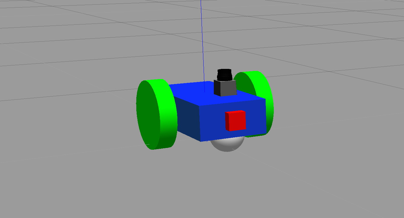
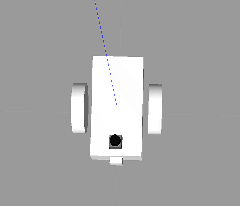
Our final robot model!
Wait, something's definitely different here.